Tuesday, 15 August 2017

Discharge Characteristics of Typical Defects in GIS

Partial discharge level is the key index for condition monitoring of GIS.  At present, UHF monitoring method is widely used to monitor PD in the gas insulated switch.
So this paper summarizes several discharge characteristics of typical defects in GIS , in order to improve the sensitivity of partial discharge test, the reasonable layout of the PD UHF on-line detector sensor, and improve the detection efficiency.
      When the high voltage rises to 20kV, the suspension metal body, which belongs to the position 1 of the discharge power source, produces a stable partial discharge. Discharge PD UHF signal from GIS exposed by the sensor measurement point P1, and record the original signal by oscilloscope and spectrum analysis, PD UHF signal and its spectrum is shown in figure 1.

time domain signal and spectrum distribution characteristics of suspended metal discharge

 Figure 1:Time domain signal and spectrum distribution characteristics of suspended metal discharge

It can be seen that the peak time peak value of partial discharge UHF signal in P1 is about 1400mV, and the duration is about 200ns. The partial discharge signal produced by suspended metal is widely distributed in frequency domain and almost covers 400MHz~2GHz, so it is easy to select the detection frequency band flexibly.
When the voltage rises to 35KV, the metal tip at the 1 position of the power source is corona, which excites the ultra high frequency signal. Recording the signals detected at P1 by oscilloscope, the time domain wave of PD and its spectrum distribution are shown in figure 2.
time domain signal and spectral distribution characteristics of point exciting discharge

Figure 2: Time domain signal and spectral distribution characteristics of point exciting discharge

      It is shown that the partial discharge extraordinary frequency signal produced by the metal tip is obviously smaller than that of the suspended metal body. The peak value of the time domain signal is about 20mV, the duration is less than 100ns, and it is obviously shorter than that of the suspended metal body. Spectrum analysis shows that the discharge spectrum of metal tip is distributed in 600MHz~1Ghz and 1.4GHz~1.7GHz.



Thursday, 3 August 2017

FAQ of DC Winding Resistance Meter


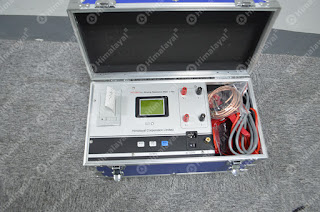
The DC resistance tester is the ideal device for the direct current resistance of the side transformer winding and the high power inductance device. In practical applications, there are also users to reflect the equipment in use will be in the process of failure. Here we explain in detail the DC resistance tester factory three problems and solutions.
DC Winding Resistance meter

1. DC resistance tester, start with the insurance fired.
There are two reasons: Winding Resistance Meter of 5A~10A,it is generally high voltage to cause transformer burn out. The instrument can not be normal in use;
The current is above 20A ,the resistance instrument appear this kind of circumstance, there is usually a problem of switching power supply.
Burn insurance occurs, only the timely replacement of transformers or switching power supply can be used normally. In the maintenance of equipment, it is necessary for professional engineers to disassemble the equipment. If the site does not have the maintenance conditions, it needs to be returned to the factory for maintenance.
2. Use DC resistance meter, but it can not measure the resistance value.
There are two kinds of reasons that can not be measured. 1. the switching power supply is broken, no current output; 2. the set value is beyond the equipment range, the program can not recognize the instructions.
If the power is damaged, replace the power supply. If it is over scale, restart the instrument and select the resistance or current within the range.
3. DC resistance meter in the testing process with blurred screen.
DC resistance meter with blurred screen may be bad connect inside the instrument .Shutdown to check whether the cable loose, reinforcement cable can solve the problem.
Another possibility is that the screen display is abnormal due to electromagnetic interference. If this is the reason, simply contact the manufacturer and add a filter capacitor.
In addition to the quality of the equipment itself, improper handling methods and storage methods can also cause equipment damage. In the process of using, can not contact the LED screen with high temperature, before testing, check whether the input interface clamp is normal or not. In addition, keeping the equipment dry and clean is also an effective way to extend the service life. In addition, it is best to correct the equipment once a year to ensure the accuracy and stability of the measurement.

HCL2796 Single PhaseTransformerTurn Ratio Meter Self check


HCL2796 Single PhaseTransformerTurn Ratio Meter Self check